Aerospace engineer working on aerodynamics and aeroacoustics: how air and sound move around and through aircraft and engines, from acoustic liners and high-lift flows to fast CFD and machine-learning surrogates.
PhD in Mechanical and Aerospace Engineering (aeroacoustics) · CFD and aerodynamics · Liner tests at NASA Langley · Patent application WO 2025/128348 A1

Aerodynamics and aeroacoustics first, then the wave physics behind them, from my PhD and the $30M NSF-funded NewFoS Science and Technology Center.
Focus areas: aircraft and engine aerodynamics, aeroacoustics, and noise reduction.
I have done substantial ANSYS CFD work, including external-flow studies of aerofoils, alongside advanced graduate CFD coursework.
In AeroPhon I rigged the NASA CRM-HL in landing configuration, recovering the slat and flap positions from NASA’s positioning files (screw-motion kinematics, gap solved to 0.02 mm), and solved the flow with the lattice Boltzmann solver FluidX3D (D3Q19) on one laptop GPU: 38 million cells at 8° angle of attack, with Q-criterion views of the slat, nacelle and wing-tip wakes. The force path is validated against Stokes drag to 3.9 %. The grid Reynolds number is below flight, so it does not predict high-lift coefficients.
AeroPhon CFD → Try AeroPhon live → Inside a Turbofan film → Aerofoil and slat drawings →
For vehicle aerodynamics, neural surrogates trained on DrivAerNet CFD cars predict drag, surface pressure and wall shear; the drag model explains about 80 % of the drag variation on 825 held-out cars (R² 0.80, MAE 0.0083).
My PhD (Mechanical and Aerospace Engineering, Oklahoma State, 2019–2024) was on acoustic liners. I designed thermoacoustic liner test articles and test matrices for NASA Langley’s normal-incidence tube and grazing flow impedance tube, with grazing flow up to Mach 0.5, and analysed the results; Langley operated the facility.
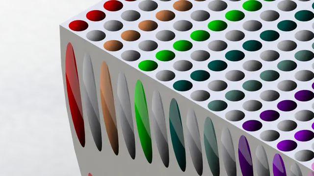
A liner is a field of small resonators under a perforated face sheet. A quarter-wave cell absorbs best when its depth is a quarter of the wavelength, so the fan’s blade-passing tone sets the depth.
IJA paper → Liner calculator → Jet-engine noise film → Acoustic liners deep dive →
Biswas S., Kresl W., Manimala J. M., “On the relationship between acoustic absorption and temperature gradient in a thermoacoustic liner”, International Journal of Aeroacoustics, doi:10.1177/1475472X241306317.
What the film shows. A single 3D-printed liner cell with a thermoacoustic stack inside, tested in the normal-incidence tube at NASA Langley. At 790 Hz and 140 dB the two faces of the stack settled 9.5 °C apart, and in sweeps from 400 to 1,000 Hz the cell absorbed 51 to 66 % of the incoming sound energy. Where the stack sits matters: the best heat came about 4 cm below the opening. At 150 dB the difference reached about 25 °C, and a linear model holds only up to a drive ratio of about 3 %. An illustrative simulation of one stack pore (not from the paper) shows the gas temperature in the pores swinging by about half a degree every cycle.
The machines that made me an engineer · rendered at my desk
Two browser-based design tools I wrote from the physics up. Both run in the browser, with no install and no API keys.
What AeroPhon’s network sees in a car: the real DrivAer reference body, sampled as 2,048 surface points, goes into a graph neural network, and the drag coefficient and surface pressure come back in seconds instead of hours. On 825 cars it never saw in training it explains about 80 % of the variation in CFD drag (R2 0.80). Try it live → · Watch in 1080p →
Phononic-plate bandgaps, designed from a plain-English prompt.
Describe or sketch a car, then test it like an engineer.
A finite-element band-structure calculation for one phononic-plate design takes minutes to hours. Neural surrogates trained on COMSOL data return the same quantities in milliseconds, so a whole design space can be searched.
Physics-informed terms in the training loss (PINNs) cut unphysical predictions, and the same models run in reverse for inverse design: from a target bandgap to a geometry. On a BOROFLOAT 33 glass plate the surrogate, FEM and measurement agree on a 195–214 kHz bandgap.
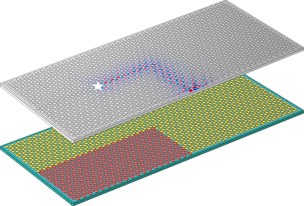
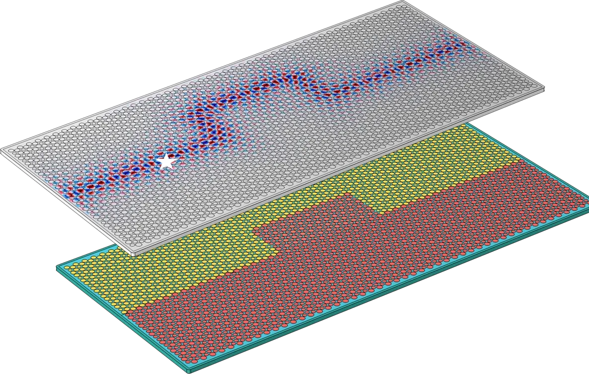
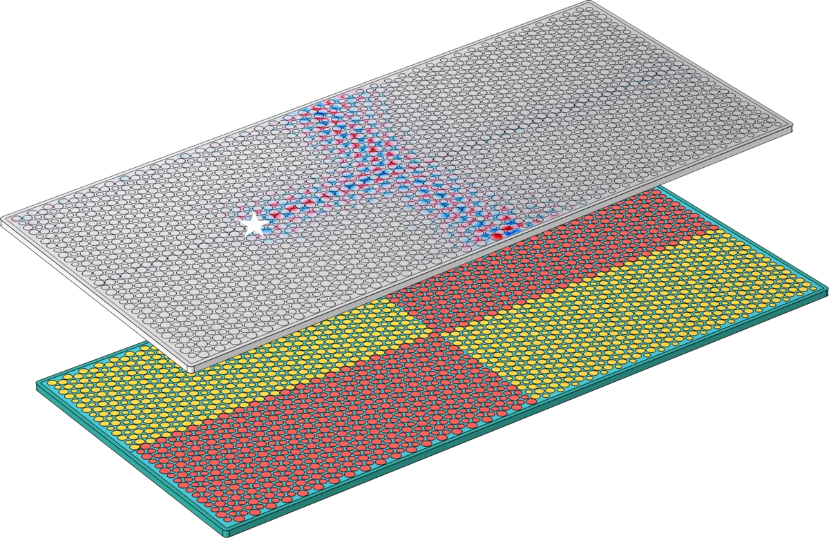
Where two acoustic lattices of different topology meet, waves can be bound to the interface. In our Scientific Reports paper these interface modes carry a pseudospin that locks their direction of travel: spin-momentum locking.
The platform is one plate of the phase-change material Ge2Sb2Te5 (GST): crystalline inclusions in an amorphous host, near 200 MHz. The simulated interface signal stays more than 35 dB above the bulk over 15 wavelengths, round bends and junctions. Two forces a quarter-cycle apart pick the direction; swapping them reverses it. The results are computational (COMSOL); experiments are next.
Biswas et al., Scientific Reports (2026) → Topology explainer →


Simulated field on the plate (top) above its domain layout (bottom); the star marks the source. From Biswas et al., Scientific Reports (2026), supplementary material.
Phononic lattices built on the Su-Schrieffer-Heeger (SSH) model host edge modes that are protected against some kinds of disorder, and they do it at room temperature with ordinary sound.
Because the wave equations map onto each other, these lattices let us test topological ideas on the bench, with measurable displacements and phases, before anyone builds a quantum device.
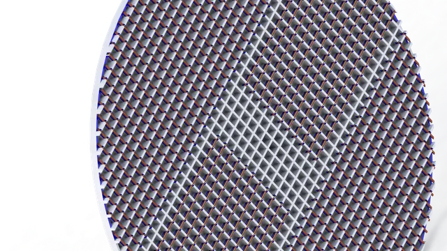
Surface-acoustic-wave (SAW) filters are how a phone separates one radio band from the next: the radio signal briefly becomes a sound wave on a piezoelectric chip.
I model how periodic structures on a piezoelectric substrate guide and filter these waves, with COMSOL simulations and machine-learning surrogates that make the design search faster.
The same rigged aircraft as the film, on a finer grid: 424 × 636 × 141, so 38 million cells (the film’s sweep uses 15.6 million) at 8° angle of attack, on one laptop GPU. Drawn as isosurfaces of the Q-criterion coloured by velocity, which isolates where rotation dominates strain, so these are the vortices rather than the whole velocity field. Tubes shed from the slat gaps, the nacelle and the wing tip. The first 1.6 flow-throughs are discarded, so this is the developed wake and not the starting transient.
Three views: top-down, where the wing and slat wakes separate most cleanly; a wide three-quarter; and a close pass on the slat and nacelle. Solver: FluidX3D, D3Q19, FP16C with a Smagorinsky subgrid model, RTX 5070 Laptop. The force path is validated against the closed-form Stokes drag to 3.9 %.
On what this is and is not. The cell is 152 mm, so the vortices cannot be finer than roughly half a metre and the surface staircase is the voxelised geometry, not the flow. The 4th AIAA High-Lift Prediction Workshop puts the requirement above 250 million degrees of freedom, which this is 6.6× short of, and the grid Reynolds number of 105 sits 331× below flight. This grid resolves separation but not attachment: the wing wake is many cells across and genuinely captured, while anything attached to a surface is not. It is a real solve at a resolution chosen so hundreds of riggings fit in the cost of one high-fidelity case, and it is not a prediction of high-lift coefficients.
My PhD work on liners and barriers that absorb sound and harvest part of it as heat and electricity, and my M.S. work on car panels that store energy. All projects →
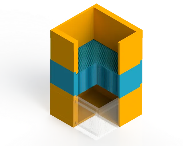
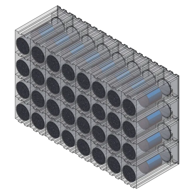
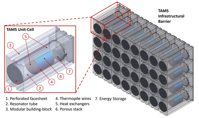
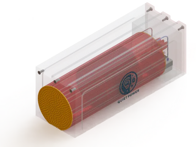
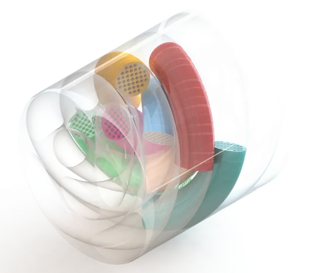
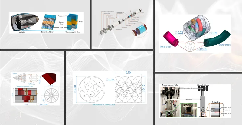
Resonator cavities with a thermoacoustic stack inside: the sound sets up a temperature difference across the stack, which a thermopile turns into a small voltage, while the cavity absorbs the sound.


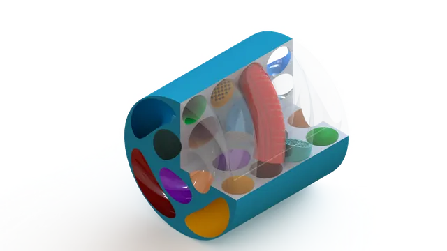
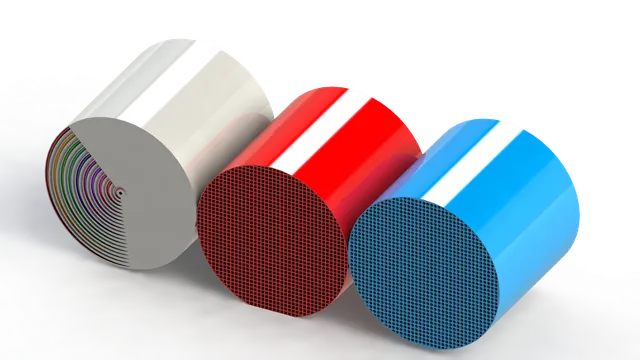
Wedge-shaped cavities that guide sound in one direction and keep neighbouring modes apart.
A helical path that lengthens the resonator without enlarging it and spreads the acoustic energy evenly.
A spiral stack that packs a long thermoacoustic path into a small volume, for control over both the wave and the heat transfer.
Concept films from my PhD work on thermoacoustic metastructures. The test rig and the metastructure are on the Projects page →
Where thermoacoustic metastructures could be used: urban noise barriers, aircraft liners, and spacecraft with large temperature gradients. The liner concept is aimed at engine tones below about 1 kHz, where conventional liners struggle. It is a concept: the liner has been tested on the bench and in NASA Langley impedance tubes, and it has not been engine-tested.
Sound sets up a temperature difference across the stack, heat exchangers carry the heat in and out, and a thermopile turns the gradient into a small voltage. On the bench the largest difference was 24.8 °C at 117.5 Hz with a resin stack; a separate experiment gave about 33 mV from the thermopile. The film below follows one gas parcel round the cycle.
A structural supercapacitor is a composite panel that carries load and stores charge at the same time. I made carbon-fibre electrodes, functionalised them by CVD and plasma treatment, and tested the panels electrochemically and mechanically.
Measured on the composite: 53.58 mWh/kg energy density, 32.06 W/kg power density and 6.9 GPa flexural modulus. That makes it a power buffer that saves weight, not a replacement for the battery.
How it works. Two carbon-fibre electrodes carry the mechanical load and hold the electrical charge. A structural electrolyte between them passes load and ions from one to the other, and a thin separator keeps the electrodes from touching while the ions move through it.
Aerospace engineer working on aerodynamics, aeroacoustics and vibration, using CFD, testing and machine learning to make design faster.
I am a Research Scientist III at the NSF New Frontiers of Sound (NewFoS) Science and Technology Center, University of Arizona. I work where flow, sound and structure meet: CFD on aerofoils, high-lift aircraft and vehicles (ANSYS, FluidX3D), acoustic liners tested at NASA Langley, and machine-learning surrogates that return a design answer in milliseconds.
My PhD at Oklahoma State University (2019–2024) developed thermoacoustic metastructures, liners that absorb engine noise and turn part of it into heat and a small voltage. The work is published in the International Journal of Aeroacoustics and filed as a PCT patent application (WO 2025/128348 A1, pending). From 2021 to 2024 I also managed the university’s vibration and acoustic test facility, more than $300K of equipment, and I have mentored seven students.
Focus areas: aircraft and engine aerodynamics, aeroacoustics, and noise reduction.
Backed by the AeroPhon CRM-HL and DrivAerNet work and the NASA Langley liner tests above.
The simulation, test and software tools I use day to day.
Each film follows one project from physics to hardware, built from 3D renders of the real geometry and blueprint animations: aircraft and engine noise, turbofans and the Concorde intake, acoustic liners, thermoacoustics, phase bits and surface acoustic wave filters. The message-journey and supercapacitor films sit with their research above.
Can a classical sound wave carry information the way a qubit does? The logical phi-bit, the quantum-analogue idea at the heart of NSF NewFoS.
One loud note makes one face of a stack hot and the other cold: the thermoacoustic cycle, our helical meta-stacks and the thermopile.
Bigger, slower fans lower the blade-passing tone, and today's acoustic liners struggle below about a kilohertz.
A GE90 on a 777 from rest to take-off: starter, light-off, the fan's climbing tone and the jet's roar. Engine internals and start timing are illustrative.
From the 727 to the 777-9: bigger, slower fans lower the blade tone, and the liner cells that absorb it have to get deeper.
How engineers quiet airliners: high bypass ratios, shaped fans and vanes, chevrons, acoustic liners and ICAO limits.
A laser-drilled honeycomb of holes turns a borosilicate glass plate into a phononic crystal. Model 195 to 214 kHz, measured 193 to 211 kHz.
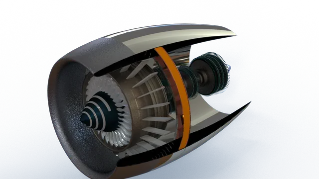
Station by station through a modern turbofan: fan, compressors, combustor, turbines and nozzle; pressure ratio, bypass ratio, cooling and the geared fan.
How Concorde's Olympus 593 breathed at Mach 2: variable intake ramps, shocks, a converging-diverging nozzle, reheat and fuel transfer for trim.
A McLaren 720S and its GT3 racing version in the same virtual wind tunnel: one lattice Boltzmann simulation on a laptop GPU, 73 million cells at about 250 km/h. Every flow shot comes from that simulation: swirl, arrows, oil-flow streaks and the slow wake. Wheels held still and a scaled Reynolds number, so it shows how the shapes treat the air, not drag numbers.
NASA's X-59 is built to fly faster than sound with a soft thump instead of a loud boom. A supersonic flow simulation (SU2, Mach 1.4) around a simplified X-59 shape: the shock cone, air carried along the solved flow, a slice sweeping down the cone and the pressure one body length below. Inviscid and simplified, so it shows the kind of shock pattern, not NASA's official signature.
On final approach an airliner's engines are almost at idle, yet the airframe is about as loud. An A350 flies the real runway 26 approach into Phoenix, and my lattice Boltzmann simulations on NASA's CRM-HL research model show the landing gear, slat cove and flap edge making sound. The simulations are Reynolds-number scaled: they show the mechanisms, not certified levels.
How acoustic liners work: Helmholtz and quarter-wave cells, impedance, double layers, grazing-flow testing at NASA Langley, and why low tones need deep cells.
From wafer to filter: how a surface-acoustic-wave filter is made and how its fingers pick one radio band.
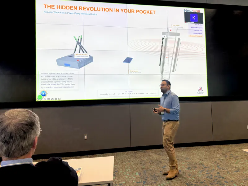
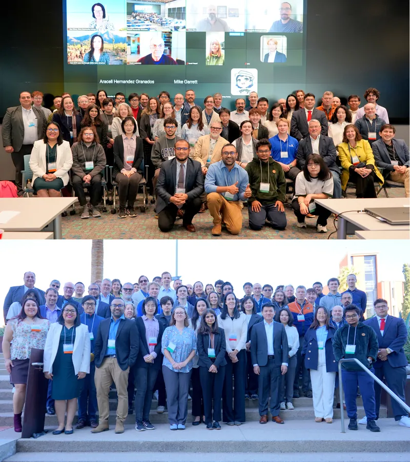
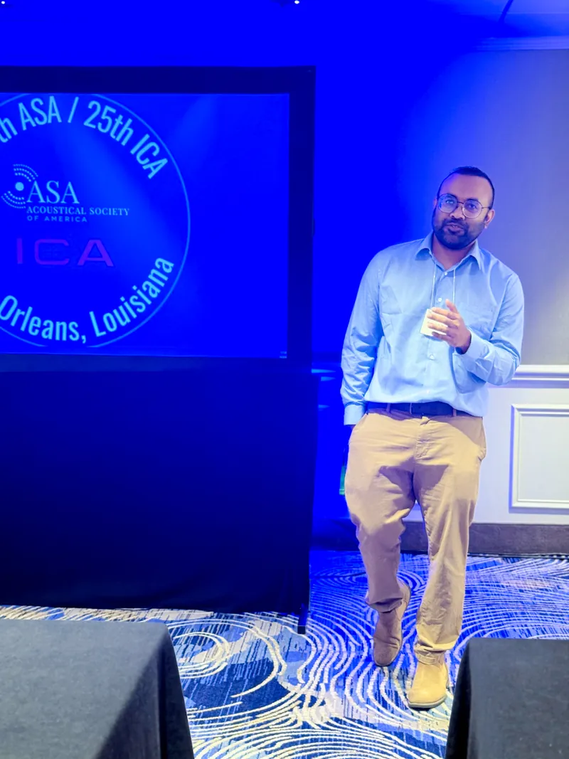
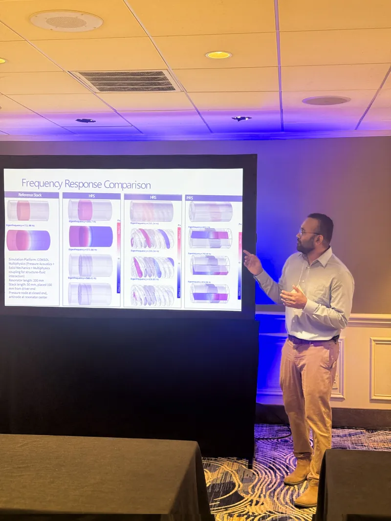
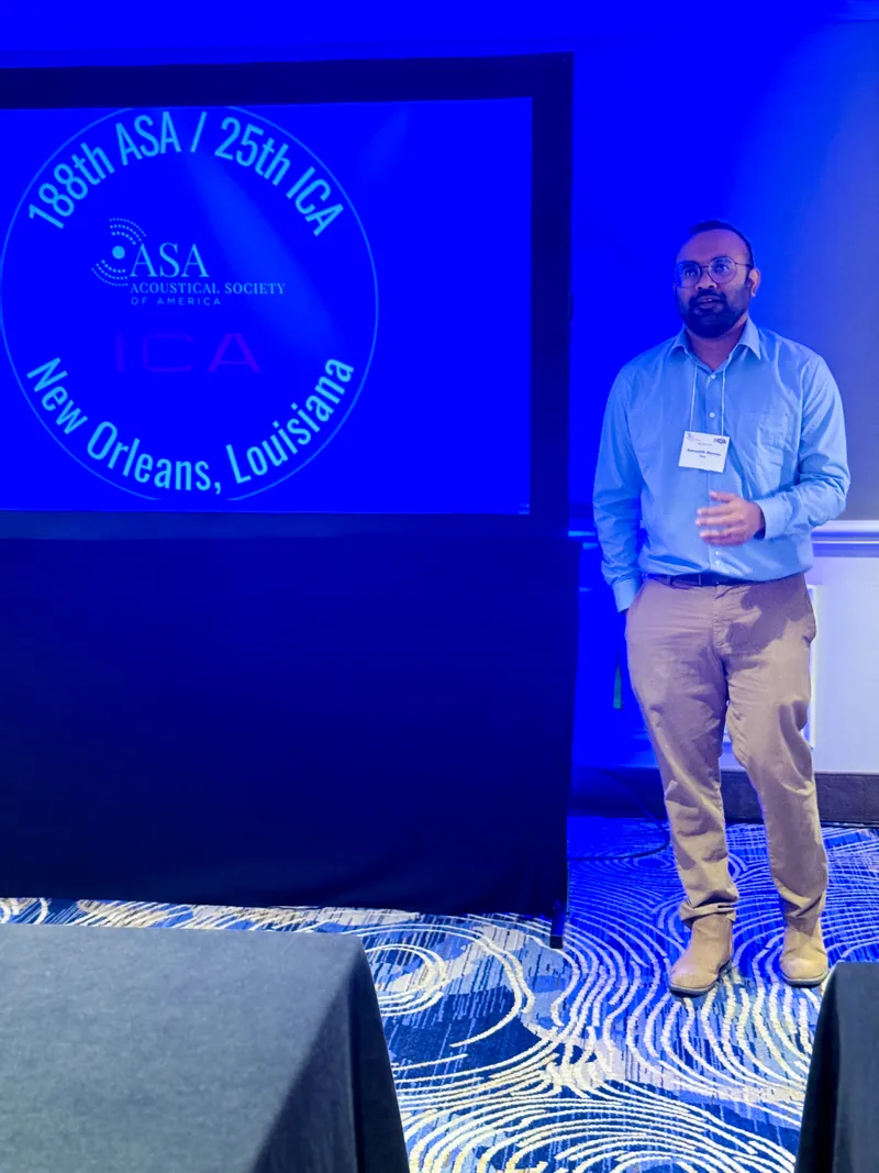
Talks, conferences and team meetings.


Outside work I draw the machines I grew up admiring, from the Wright Flyer to the Space Shuttle. Every plate is traced from a real 3D model, museum scan or NASA drawing.
Open to roles and collaborations in aeroacoustics, vibration, acoustic liners, RF acoustic devices and simulation.